This is the english manual for the PIC-Flash 84 and the PIC-Flash II programmer. Both are
PC-based programmers for the PIC-Family from Arizona Microchip. The difference
between 84 and II is that the 84-model is a development-programmer for PIC 16x8x only and II is a
production-type programmer for (nearly) all ISP-capable devirates.
For 84 there is a free software for DOS and Windows 9x available for download. The II software is only available for DOS
and requires payment of a small fee. However, you can find a limited evalution version also on this website.
|
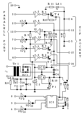
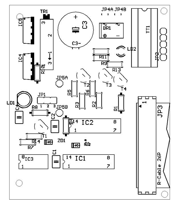
If you want to build an 16x8x- or Development-type programmer only you can leave away 'IC 1' along with 'T 1', 'ZD 1', 'R 1' and R 2. In this case put the jumper towards the border of the board (towards the middle if you use PIC-Flash II as a Production-type programmer).
| Signal | ISP-Connector (Assignment is printed on the PCB !) | 8-pin DIL On-Board combined with 18 pin | 18-pin DIL (On Board) | 28-pin DIL | 40-pin DIL |
|---|---|---|---|---|---|
| MCLR / VPP | 1 | 4 | 4 | 1 | 1 |
| VCC | 2 | 1 | 14 | 20 | 11 & 32 |
| GND | 5 | 8 | 5 | 5 & 19 | 12 & 31 |
| Data (RB7) | 3 | 7 | 13 | 28 | 40 |
| Clock (RB6) | 4 | 6 | 12 | 27 | 39 |
The socket for the PIC should be ZIF-type. This extends the pins' lifes, is more comfortable and reliable than a normal one. If you could not get one with rounded pins just solder a pin row between PCB and ZIF. If you have a model with 20 pins just leave the two next to the lever empty - all PICs use the same pin for pin 1 !
After building check both voltages in every case. The 74's use 5 volts - measure between pins 14 (Vcc) and 7 (GND). The programming voltage at the output of the LM 317 should be 13.0 volts - adjust using P1.
The cable between PC and programmer should be no longer than 1 meter, use a shielded one if possible. At the programmer's end a post connector has to be used, the 25 pin Sub-D connector at the PC can be crimped or solder wires #2-9, #12 and #17-19 to a normal one.
| Schematic | # | REF DES | Description |
|---|---|---|---|
 |
74 LS 14 (C-MOS-Inverter with Schmitt-Triggers) | ||
| 74 LS 06 (TTL-Inverter with open collector) | |||
| LTC 1257 CN8 (Serial 12 BIt-DAC) OPTIONAL ! | |||
| LM 317 (Adjustable voltage regulator 1.2 - 30 V) | |||
| 7805 (fixed voltage regulator + 5 V) | |||
| Transistor 2N3904 | |||
| Transistor BC 328-25 | |||
| Transistor BC 557 B | |||
| Bridge rectifier 40 V / 0,5 A | |||
| Zehner diode 10 V / 0,5 Watt | |||
| Schottky diode BAT 43 | |||
| LED green (indicates PIC access) | |||
| LED red (indicates power supply) | |||
| Trimmer 10 K-Ohm | |||
R 13 | Resistor 10 K-Ohm / 0.125 watts | ||
R 9 | Resistor 4,7 K-Ohm / 0.125 watts | ||
| Resistor 2 K-Ohm / 0.125 watts | |||
R 14 | Resistor 220 Ohm / 0.125 watts | ||
| Resistor 560 Ohm / 0.125 watts | |||
| Capacitor 100 nF | |||
| Electrolyte Capacitor 2200 uF | |||
| Jumper, soldering nails, transformer, ZIF-socket, connectors, ribbon cable and PCB, see text |
 |
| Attention: In the OS/2-DOS-Box it's required to set HW_TIMER to on ! |
A few notes about using the software (PIC Flash II - the windows version should be self explaining):
Before loading/saving/reading/writing you have to select the right PIC type in the 'PREFS'-menu. It's also neccessary to select the printerport to which the programmer is connected and to lay down, if the fuses and the data EEPROM should be loaded/saved with the hex (or binary) file. 'Read/Write' code/data/fuses can exclude reading/writing these areas. These settings - along with the PIC-type and size - are also displayed at the bottom of the 'I/O'-Screen.
'Chip erase' only works for Flash devices, it's normally not neccessary to erase a flash device as long as it has not been code protected.
In the 'Fuses'-menu fuses can be changed and displayed. Please be aware that you have to select the right PIC in the 'PREFS'-menu to ensure that this feature works
correct.
The power settings are the same for all devices. Normally leave programming Vcc at 5.0 volts, minimum voltage at 4.5 and maximum at 5.5 volts. These values don't care if you
operate the hardware in the development-mode. Edit them only if you are using a PIC with a different voltage range.
Since software version 1.15 you can access the new hardware test feature using the 'T'-key inside the 'EXIT'-menu.
First set Vcc to 5.00 volts then check it along with Vpp (should be adjusted to 13.00 volts at the MCLR-pin). Afterwards - without
changing Vcc - you can check the data and clock lines. Data input should follow the data line output.
The programmer itself should also only be connected or disconneted to the PC while both are turned off.
The software accepts HEX-files (extension '.hex') in the INHX8M-Hex-Format which is also used by 'MPASM' from Arizona Microchip. Starting version 1.19 you can
specify this hex-file at the commandline, too. Be sure to save an suitable config before using this option.
Other:
Never insert or remove a PIC while it's being accessed by the programmer (green LED on) ! The software turns if off right after startup and after each I/O-operation.
Contact:
The autor is happy about each E-Mail mit praise, constructive criticism and so on.
| Last Update: 04-08-1999 | (C) 1997-99 by G. Mueller |
Homepage: http://uC-Project.de |